Category
Description
Friction Stir Welding Processing
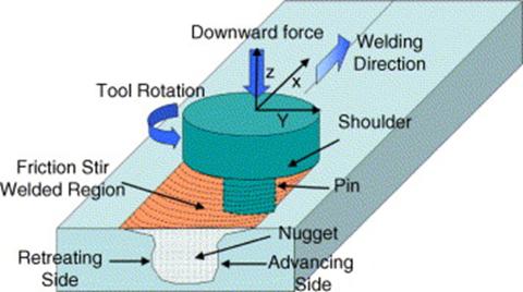
Friction Stir Welding (FSW) is a solid-phase joining process achieved by spinning a tool and plunging it into the weld site. Frictional heating and material deformation enable the formation of a plasticized region below the tool shoulder called the stir-zone. The FSW tool and stir zone are traversed across the joint effectuating a weld. Friction Stir Processing (FSP) is the use of FSW for purposes other than joining such as material property modification and repair. 1
Time series and column header data is gathered from the FSW Human Machine Interface Controller (HMI) and combined into one single Excel (.xlsx) file. The .csv file contains only "Raw Time Series" data from the Excel document and is created for machine use. Excel and csv metadata. Learn more about the post-processing process here.
Proper handling of in flight data protects the investment of staff time and time and is important not just for the final archived at rest data. The more detail we can provide about the data (i.e. its provenance, structure, meaning) only increases the value and FAIR-ness of the data. Attempts are made to generate colorblind accessible plot visualizations. See a quick summary of FAIR data here
Dataset Description
Naming Hierarchy 2
-
Plate: The physical metal plate with desired mechanical properties (such as Stainless Steel 316) chosen for application of the FSW process and evaluation of metallurgical effects of the process. The name of a plate number is structured as follows:
YYYY MM DD XXwhereXXrepresents the nth run of the day. Example of plate number:2022 03 02 05. Plate number2022 03 04 0005/0007corresponds two different welds that were performed on the same plate. Additional characterization plate data -
Sample: The portion of the plate on which a specific defined FSW process condition is applied. One of a set of eleven related FSW processing conditions (e.g. speed, force, temperature) enumerated by
C01throughC11is applied to the sample. A twelfth control (unprocessed) condition is enumerated asC00. Multiple conditions (typically four) may be applied when processing a single plate, each change in condition resulting in a distinct sample. Samples are identified by Sample IDs such asSS01,SS20, etc. Additional characterization Round 1 Weld Condition data -
Specimen ID: A specimen is cut from a Sample for evaluation by destructive and non-destructive means using modalities such as microscopy and ultrasonics. Specimens are indicated by values such as MCPC0001, MCPC0157, etc. and specimens from the same sample are metallurgically identical. The Specimen ID is physically stamped onto each specimen (along with an orientation mark) for identification. Specimen ID is assigned starting at Sample 1 with MCPC0001, MCPC0002, etc in chronological order, continuing with Sample 2 and so on. Analysis of these specimens can be found in the Characterization datasets.
-
Dataset ID: Each individual Dataset ID represents application of a modality to characterize a specimen. Multiple datasets may be used for a characterization. The Dataset ID is unique within measurements of a modality but is not required to be unique across modalities. The ID in the case of microscopy is associated with the "mount number" written in the acrylic when the specimen is mounted and polished. The ID for ultrasonics is a "scan number" assigned by the operator and written in logs and associated with file naming. Replicate or repeat measurements of the same specimen are curated with a different Dataset ID.
Files and Directories
- README, LICENSE, DISCLAIMER, FSW Data Supplemental README.pdf
- METADATA_LISTING.xlsx -- Description of plates, samples, and conditions
- DATA
- Processed_Datalogs -- xlsx and csv formats
- {plate name}.xlsx
- {plate name}.csv
- README.md
- Timeseries_Datalogs -- xlsx formats
- Hardness Timeseries Data
- Microscopy Timeseries Data
- NDE Timeseries Data
- README.md
- Processed_Datalogs -- xlsx and csv formats
- VISUALIZATIONS
- CUT_PLANS
- README.md
- {plate name} cut plans
- {plate name} cut plans in pdf, dxf, solidworks formats
- FSW CAD Geometry -- CAD files
- STL -- folder with STL files
- STEP -- folder with STEP files
- README.md
- KEYENCE_TOOL_SCAN_REGISTRY.xlsx -- Maps CAD files to plates
- ENSEMBLE-INFO
- VR-5000.pdf
- CUT_PLANS
Methodological Information
- 3D Scans
- Wide-area 3D Measurement System, VR Series
- Keyence 3D scanning machine, 'VR-5000'
- Friction stir welds
- Data in the "key variables tab" in the Excel files have been post-processed to ensure only relevant fields are used for analysis (e.g. unnecessary thermocouple fields have been removed)
- Data in the "key variables tab" are transformed into the process coordinate system (please see "FSW Data Supplemental README.pdf" for definitions of cordinate systems)
- Welds are running using robust temperature control and force control (https://doi.org/10.1007/978-3-319-52383-5_26)
- A pilot hole is used to reduced forces durign the plunge. A 118° 1/2 inch diameter drill bit is used to drill the pilot hole such that the tip (point) of the drill bit reaches a depth of 0.130 inches.
- For all timeseries data the 0 location is the plunge location for the first weld done on each plate. This is 1 inch from the edge of the plate for all plates. for plates where a weld was aborted and restarted, the weld traverse postion is still based on =0 1st weld start (which is 1" from the plate edge)
- Please contact Kenneth Ross or David Garcia with question about weld setup, weld data, or intepretation of such
- Software version: Solidworks 2019 or edrawing 2019
Authors
- Kenneth A. Ross kenneth.ross@pnnl.gov
- David Garcia david.garcia@pnnl.gov
- Donald Todd donald.todd@pnnl.gov
References
- Ross, Kenneth A., and Alabi, Morotolaoluwa. Update on Investigations of Viability of Cold Spray and FSW as a Spent Nuclear Fuel Dry Storage Canister Mitigation Tool. United States: N. p., 2019. Web. doi:10.2172/1580110.
- Todd, Donald. MCPC Characterization README. {insert DOI here}
Appendix
Weld Conditions
Excerpt from "METADATA_LISTING.xlsx"
| Condition | Temperature (°C) | Traverse velocity (ipm) | Force (lb) |
|---|---|---|---|
| C00 | N/A | N/A | N/A |
| C01 | 720 | 0.5 | 9000 |
| C02 | 720 | 0.5 | 10500 |
| C03 | 720 | 1 | 10500 |
| C04 | 720 | 1 | 9000 |
| C05 | 720 | 3 | 10500 |
| C06 | 750 | 1 | 10500 |
| C07 | 750 | 3 | 10500 |
| C08 | 800 | 1 | 10500 |
| C09 | 800 | 3 | 10500 |
| C10 | 850 | 1 | 10500 |
| C11 | 850 | 3 | 10500 |
Plate with Sample Characteristics
Excerpt from "METADATA_LISTING.xlsx"
| Plate | Sample | Temperature (°C) | Traverse Velocity (ipm) | Force (lb) | Condition |
|---|---|---|---|---|---|
| 2022 03 02 05 | SS01 | 720 | 1 | 10500 | C03 |
| 2022 03 02 05 | SS02 | 720 | 3 | 10500 | C05 |
| 2022 03 02 05 | SS03 | 750 | 1 | 10500 | C06 |
| 2022 03 02 05 | SS04 | 750 | 3 | 10500 | C07 |
| 2022 03 02 0009 | SS05 | 800 | 1 | 10500 | C08 |
| 2022 03 02 0009 | SS06 | 800 | 3 | 10500 | C09 |
| 2022 03 02 0009 | SS07 | 850 | 1 | 10500 | C10 |
| 2022 03 02 0009 | SS08 | 850 | 3 | 10500 | C11 |
| 2022 03 02 0017 | SS09 | 720 | 1 | 10500 | C03 |
| 2022 03 02 0017 | SS10 | 720 | 3 | 10500 | C05 |
| 2022 03 02 0017 | SS11 | 750 | 1 | 10500 | C06 |
| 2022 03 02 0017 | SS12 | 750 | 3 | 10500 | C07 |
| 2022 03 02 0019 | SS13 | 800 | 1 | 10500 | C08 |
| 2022 03 02 0019 | SS14 | 800 | 3 | 10500 | C09 |
| 2022 03 02 0019 | SS15 | 850 | 1 | 10500 | C10 |
| 2022 03 02 0019 | SS16 | 850 | 3 | 10500 | C11 |
| 2022 03 04 0005/0007 | SS17 | 800 | 1 | 10500 | C08 |
| 2022 03 04 0005/0007 | SS18 | 800 | 3 | 10500 | C09 |
| 2022 03 04 0005/0007 | SS19 | 850 | 1 | 10500 | C10 |
| 2022 03 04 0005/0007 | SS20 | 850 | 3 | 10500 | C11 |
| 2022 03 07 0009 | SS21 | 750 | 1 | 10500 | C06 |
| 2022 03 07 0009 | SS22 | 750 | 3 | 10500 | C07 |
| 2022 03 07 0009 | SS23 | 720 | 1 | 10500 | C03 |
| 2022 03 07 0009 | SS24 | 720 | 0.5 | 10500 | C02 |
| 2022 03 07 0011 | SS25 | 750 | 1 | 10500 | C06 |
| 2022 03 07 0011 | SS26 | 750 | 3 | 10500 | C07 |
| 2022 03 07 0011 | SS27 | 720 | 1 | 10500 | C03 |
| 2022 03 07 0011 | SS28 | 720 | 0.5 | 10500 | C02 |
| 2022 03 07 0013 | SS29 | 750 | 1 | 10500 | C06 |
| 2022 03 07 0013 | SS30 | 750 | 3 | 10500 | C07 |
| 2022 03 07 0013 | SS31 | 720 | 0.5 | 9000 | C01 |
| 2022 03 07 0013 | SS32 | 720 | 1 | 9000 | C04 |
| 2022 03 08 0003 | SS33 | 720 | 0.5 | 9000 | C01 |
| 2022 03 08 0003 | SS34 | 720 | 0.5 | 9000 | C01 |
| 2022 03 08 0003 | SS35 | 720 | 0.5 | 9000 | C01 |
| C00 | SS36 | Control | Control | - |
Key variables data dictionary
- The following is a data dictionary for the Key Variables sheet. This sheet contains the most relevant and useful information for a weld according to our subject matter experts. This applies to sheet in .xlsx files in DATA/processed_datalogs
| COLUMN | DEFINITION | UNITS |
|---|---|---|
| Time | Duration of a weld | mm:ss |
| Time(s) | Duration in seconds of a weld | seconds |
| Traverse Position | Total distance from weld start | millimeter |
| Forge Position | Plunge depth of tool | millimeter |
| Traverse Velocity | Speed of tool motion in the direction of the weld | millimeter/minute |
| Forge Velocity | Velocity of tool in out of plane direction used to maintain constant forge force | millimeter/minute |
| Traverse Force | Reactionary forces measured on the tool parallel to tool motion direction | N |
| Cross Feed Force | Reactionary forces measured on the tool perpendicular to tool motion direction | N |
| Forge Force | Reactionary forces measured on the tool in the out of plane direction | N |
| Spindle Speed | Tool spindle rotation rate | RPM |
| Spindle Torque | Resistive moment on tool as measured by tool spindle | Nm |
| Spindle Power | Power input by the motor to achieve tool rotation | kW |
| Traverse Power | Power input by the gantry to move tool in traverse direction | kW |
| Tool Temperature | Current temperature of the tool | Celcius |
Coordinate System:
- Data logging from the FSW machine includes many variables that are for machine control development and maintenance that are can mixed units
- Force and position data are reporting in the machine coordinate system, which is not suitable for developing and understanding of processes. Force and position data in the Key Variables tab and graph tabs are converted to a process coordinate system, described below, which is appropriate for developing and understanding of the process.
- Please see "FSW Data Supplemental README.pdf" for definitions of cordinate systems
- Please contact Kenneth Ross (kenneth.ross@pnnl.gov) or David Garcia (david.garcia@pnnl.gov) if you have question about these datalogs or about processs physics of FSW in stainless steels.
Post-Processing
- After a weld run is complete, the Human Machine Interface Controller (HMI) generates two files for each weld: one with time-series data and the other with column headers. This data is stored in a .dbf format, which is easily read and processed by excel. Excel macros are used to map raw data into usable tabular format for easy machine learning. In future data collection rounds, macros will be replaced with a Python script.
- For this round, users have gone in and manually selected the columns of interest to generate the data to be used in these datasets. Automation will be implemented in future data collection rounds.
- Data in the key variables tab of the Excel files found in DATA/processed_datalogs has been post-processed to ensure only relevant fields are used for analysis (e.g. unnecessary thermocouple fields have been removed)
FAIR Principles
The FAIR principles were originally published in 2016 in the journal Scientific Data. These principles emphasize being able to find, use, recycle, and operate on data with minimal human intervention.
FAIR stands for:
- Findable: Metadata should be easy to find for both humans and machines alike
- Accessible: Users of data should know how to access the data (i.e. what auth is needed to get it)
- Interoperable: Data needs to interoperate with apps and frameworks
- Reusable: Data should be described well enough to be replicated or used in different settings